Bosch Rexorth Valve amplifier VT-VRPD-1-1X/V0/0 R900904484 Rexroth

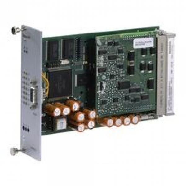
Bosch Rexorth Valve amplifier VT-VRPD-1-1X/V0/0 R900904484 RexrothThe valve amplifier is set-up as printed circuit board in Europe format 100 mm x 160 mm with daughter board, fitted on both sides.The central unit is a microcontroller controlling the entire process and realizing the position control. Data for configuration, command values and parameters are stored in a FLASH in a non-volatile form.Four binarily coded digital inputs are used to call up parameter sets (command values) from the memory in which you can store a maximum of 16 sets. A call-up activates the command value for the control spool position with the related ramp times.More control inputs have the following functions:Command value valid:Enabling of the parameter set addressed by the current call-up (H active)Enable:Activation of the outputs (acknowledgment of the fault message with low→high edge)The valve amplifier comprises a controller for the control spool position of a proportional valve.The command value can be preset via digital command value call-ups [5] and/or via analog inputs [1]. The analog input AI4 (b14/b16) is to be used for the command value presetting of ±10 V, the analog input AI6 (b22/b24) for any command value presetting from 4 to 20 mA.Command values from 0 to +10 V (12…20 mA) control solenoid B.Command values from 0 to –10 V (4…12 mA) control solenoid A.The digital command value is added to the analog command value with the correct sign, according to the set call-up.The command value inputs can be varied by means of software in the signal level.Apart from the internal ramp generation option, you can also influence the ramp for “up” and “down” from external signals with correct total and correct sign by means of the AI2 (b6/b8) and AI5 (b18/b20) analog inputs.For the valves, the software configures a step function generator [8] for the realization of the overlap jump if an overlapped control spool is selected.The command value total is switched to the controller [12]. The actual valve value (b26) is generated from the valve position measurement system by means of an oscillator/a demodulator stage and also switched to the controller [12]. The controller output controls the flow-controlled output stages.Enable and error messagesThe control is activated by the H level at the enable input. If no command value call-up is active, the digital call-up 0 is set.Error logics [15] identify any control deviation, cable break of the actual value cables and the command value input for 4 to 20 mA as well as an inactive enable input. If there is an error, a fault message is output to (d22) by means of a low signal and indicated visually by the “OK” LED (LED goes out) on the front plate. It is possible to configure the enable so that an inactive enable input is not indicated as error.Parameterization and diagnosisSelection of the valve to be controlled and selection and configuration of the command value input, the ramp generator and the
Bosch Rexorth Valve amplifier VT-VRPD-1-1X/V0/0 R900904484 Rexroth
Имя:
Телефон:
Email: *
Введите текст с картинки: 


Корзина